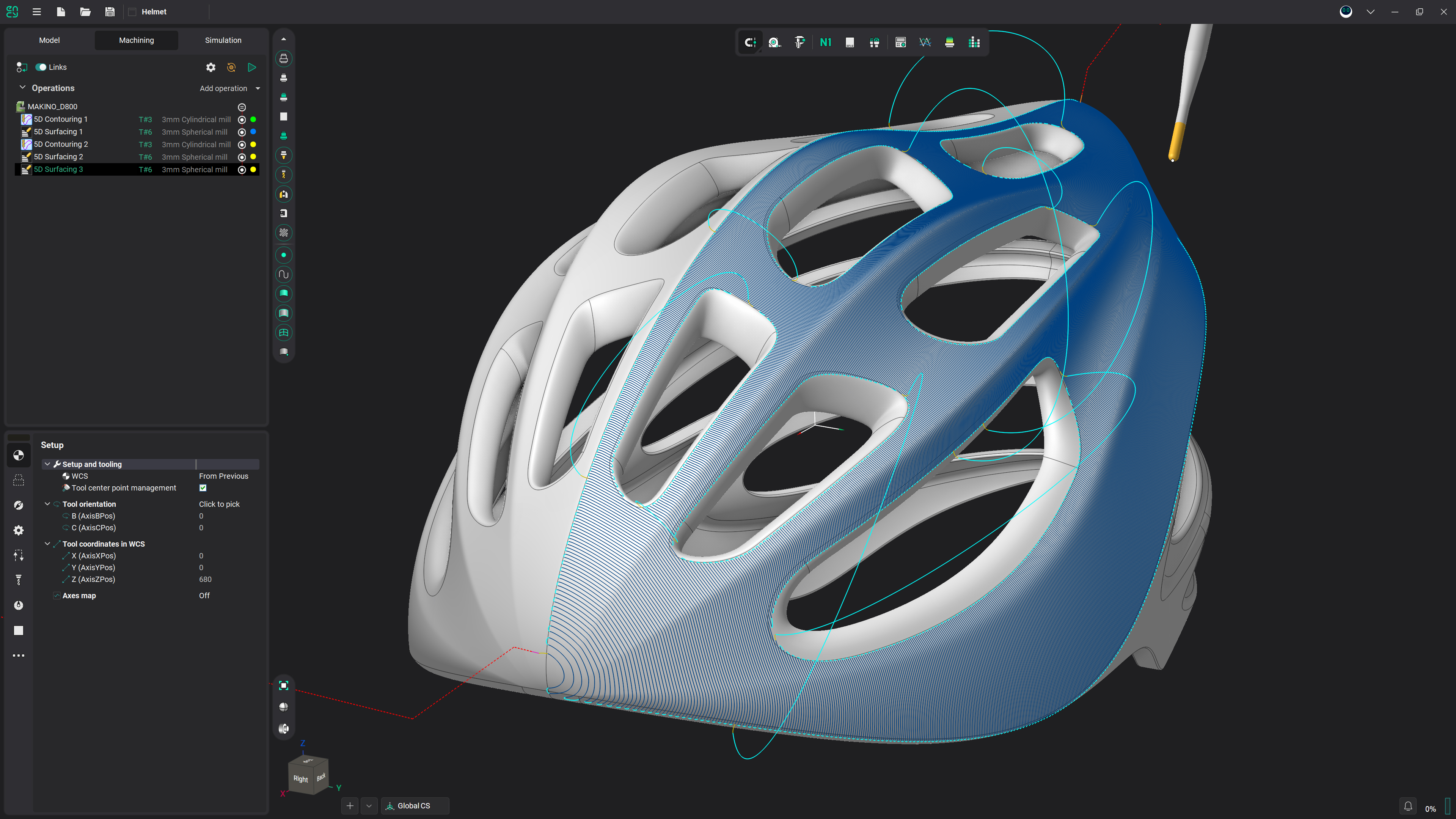
Blade Machining
A dedicated finishing operation for single blades: airfoil, root zone, hub and edges.
What Blade Machining Is
- A specialized multi-axis finishing operation for single blades of compressors, turbines and impellers.
- Machines the airfoil, the hub surfaces with fillets, the root zone and the leading and trailing edges.
- Builds passes around a user-defined rotary axis and projects them onto the part surfaces.
- Works from two geometry groups — Blade surfaces and Hub surfaces — and trims the working range with start and end margins.
Four Target Zones
- The Target zone parameter switches the operation between the structural elements of the blade, and with it the strategy, the required geometry and the visible parameters.
- Blade — The airfoil profile, machined over the whole working range in any of the three trajectory forms.
- Edges — The leading and trailing edges, found automatically as curvature peaks of the airfoil cross-sections.
- Root zone of blade — Cleanup passes next to the hub, sized by Zone height, for a smaller or tapered tool.
- Hub — The hub surfaces and fillets, in equidistant offset passes running outwards from the blade.
Pass Patterns and Side Control
- Three trajectory forms are available.
- Spiral runs a continuous helical pass; Circular and Linear section the surface perpendicular to the rotary axis or through it.
- In the Blade zone, the Linear and Circular forms machine the suction side and the pressure side together or one at a time.
- Leading- and trailing-edge margins keep the passes clear of the edge peaks.
Contact Point Control on Edges
- When machining the edges, the point where the cutter meets the surface can move along the pass instead of staying in one place.
- A fixed contact point, a shift from the start line to the end line, or a sinusoidal wave along the pass.
- Wave distribution gives the most uniform wear of the tool corner radius.
Thin Blades and Sharp Edges
- A thin blade bends away from the cutter under load, and a uniform finishing pass leaves an uncut layer near the tip.
- Bend compensation stock leaves an intentional, smoothly growing stock in the flexible region, removed by a final light pass.
- The stock profile is shaped along the blade and can be Linear, Parabolic or Sine.
- Near the edges, normal smoothing blends the contact normal before the edge and removes the jerk of the rotary axes.
- Auto min lead angle raises the tool tilt wherever the cutter bottom would start rubbing with its heel, smoothly along the pass and without steps.
Frequently asked questions
They are made for different parts. A blade is a separate component that is later assembled into the engine, while a blisk or an impeller is a single solid part — and on an impeller the neighbouring blades restrict tool access, so the passes cannot run the way they do on a standalone blade. Blade Machining finishes a single blade, with separate zones for the airfoil, root zone, hub and edges. Impeller Machining works on complete blisks and impellers and covers roughing as well as finishing, with shroud surfaces among its job areas.
Yes. A dedicated target zone machines them with longitudinal passes, and the edges are detected automatically from the airfoil cross-sections.
Machining of the shroud band on single blades has been named as a direction for the operation — an announced direction, not a shipped feature.
Typically yes. The airfoil and the area next to the hub are machined as separate operations with different tools, because the tool used for the main surface cannot reach into all of the lower zones. A larger tool runs the airfoil, and a smaller ball-nose tool cleans up the root zone.
Get started with ENCY