Columns that learned to dance: tree supports for robotic metal deposition
In FDM you pull supports off with pliers. In robotic metal deposition you cut them off with a saw, because the support is welded to the part.
By Ilnar Galiullin, Senior Software Developer
A column drops straight from the overhang to the plate, unless something is in the way. A tree support is a column that learned to dance. It leans, joins hands with its neighbours and steps around whatever sits below.
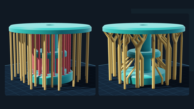
Dropped straight down 32 red columns land on the collar or the flange. The tree takes all 68 to the plate
Trees are not just an experiment. Cura, PrusaSlicer, Bambu Studio and Meshmixer ship them for plastic [1, 2, 3, 4], and Materialise added them to Magics for metal applications back in 2014 [5]. That is a good sign they work. What interests me is where they belong in robotic metal deposition, next to the other ways of holding an overhang, and how my generator grows them.
Laser-cut fixtures.
The ENCY extension store already has two excellent ones.
- Support generator builds a fixture from interlocking X/Y ribs profiled to the part's surface, with a base plate and a flat cutting layout
- Cradle generates interlocking laser-cut welding fixtures from the underside of a part, with clamp islands and weld-access zones.
They are fast, precise, reusable and cost no arc time, and they work great alongside tree supports.
What a fixture can't do is reach into a pocket under the part, grow with the part during the build, or carry a weld pool without becoming part of it. An arc needs a conductive, weldable base, and a steel rib that takes the pool fuses to it. Welders use copper backing bars for exactly this reason, and removable copper supports have been tested in DED too [6].
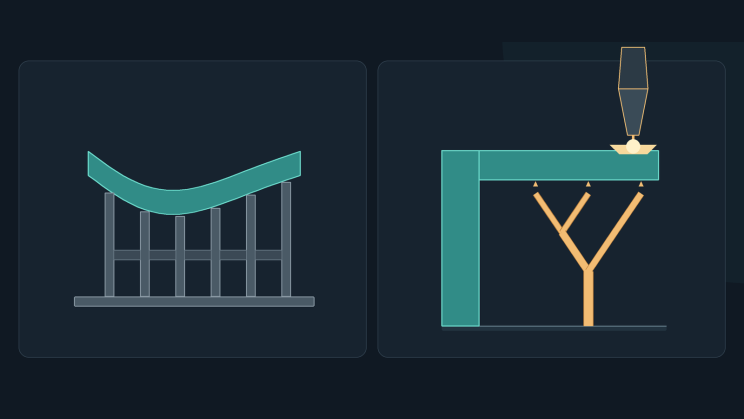
Left: a laser-cut rib fixture holds the part from the outside. Right: a deposited tree grows under the overhang, right where the torch needs a base
Deposited supports are built by the same program, in the same coordinates, and grow with the part. They reach recesses, take heat away and hold the part against distortion [7]. The price is arc time, wire and a saw.
They come in three shapes:
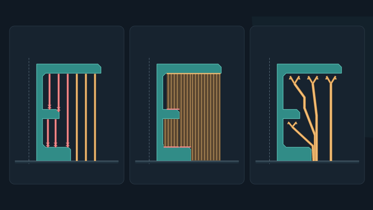
Left to right: columns, a wall and a tree on the same half-section of the demo part. Red marks where a support lands on the part
Columns are simple and predictable, and useless when anything of the part sits below. A wall is stiff, and in arc deposition it can be one continuous bead, which is a real advantage; the price is material and a big contact area to clean up. A tree touches the overhang with small tips, shares trunks and walks around obstacles; the price is slender branches and more maths.
Tilting instead of supporting.
A robot with a positioner doesn't print in 3D; it prints in something closer to 6D. Tilt the part, and an overhang becomes a wall. Tilt the torch, and you can deposit sideways. Researchers have pushed wire-arc overhangs to 105° this way [8], built overhangs onto a fixed substrate without any supports [9], and removed supports almost entirely with multi-axis slicing [10, 11].
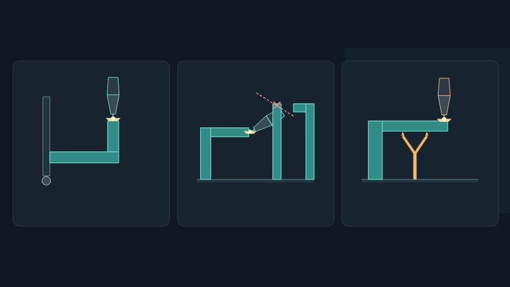
Inside a pocket, the tilted torch hits the part
That freedom has a price. A positioner has to carry and precisely orient a heavy part, and inside enclosing geometry a tilted torch simply hits what was deposited before [8]. Collision checking and machine kinematics for multi-axis paths are hard [10, 11]. So many cells stay with planar layers and a fixed torch, which is simple and stable but safe only to about 15° of overhang [12], and robotic WAAM studies note that with flat deposition, near-horizontal overhangs may still need temporary supports [13].
My rule of thumb: tilt what you can, cut a fixture for what you can reach, and grow trees for the rest. That means overhangs above other parts of the model, pockets, and heavy parts you can't flip.
How the generator grows a tree
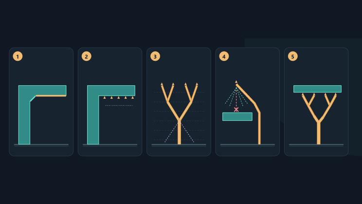
1. Find the overhangs. 2. Place the tips. 3. Merge on the way down. 4. Walk around obstacles. 5. Fuse everything into one closed mesh
1. Find the overhangs. A face needs support if it points down and tilts more than the surface angle from vertical. Faces lying on the plate don't, and very thin slivers along CAD face boundaries are ignored, because their normals can't be trusted. CAD cracks are welded shut first; open IGES sheets and scans are treated as two-sided surfaces, so they get supports too.
Faces are not the whole story, though. Tilt a flange a little, and every face around its lower rim is steep enough, yet the rim itself hangs in the air: the first layer of the flange starts there, with nothing below. The same goes for the tip of a corner pointing down. So the generator also looks for convex edges that point down and run flatter than the surface angle, and for lowest points, and puts contacts along them. Where such a rim just continues an overhang that already has tips, it reuses them.
2. Place the tips. Contacts are sampled on a grid with the chosen spacing, each a small gap below its surface. Two contacts count as duplicates only if they lie on the same local patch of surface, so two stacked surfaces a few millimetres apart each keep their own tips.
3. Merge on the way down. All tips form one front that descends layer by layer. On each layer, nodes that already carry more tips go first, and each tries its nearest neighbour first. Two nodes merge one layer lower at their weighted centre, weighted by how many tips each carries, if both can reach that point within the branch angle without touching the part. If no partner works, the node goes straight down, unless the part is in the way.
4. Walk around obstacles. When the way down is blocked, a beam search takes over (more below).
5. Fuse and check. Every branch becomes a tapered capsule, and all of them are fused into one closed mesh. Tips that can't reach the plate are listed, not silently dropped.
How the generator grows a tree
Two angles drive all of this, and they answer different questions. The surface angle decides where supports start. The maximum branch angle decides how far a branch may lean on its way down. Both come from the process, not from the algorithm: a fixed wire-arc torch is safe to about 15° of overhang [12], thin laser-DED walls stayed stable up to about 30° [14], and FDM is usually happy with 45° or more.
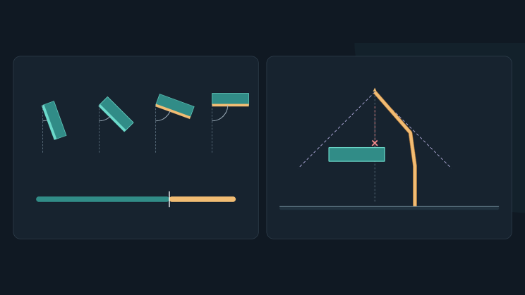
Left: faces tilted past the surface angle (amber) get supports; steeper ones (teal) don't. Right: every branch stays inside the cone set by the maximum branch angle
From every partial route, the search tries 25 places on the next layer: straight down, plus two rings of 12 directions whose radius comes from the branch angle. A route is expensive while the part is still below it; sideways distance and length add a little. The search keeps the 24 cheapest routes and, separately, the outermost route in each of the 12 directions. Without that, a route that has to crawl sideways under a broad ledge looks too expensive and dies, even when it's the only way out. Once the column below a route is clear, the rest of the drop is proven in one check. If nothing is found, the search runs again with half the step, and a trunk that got stuck after a merge is split back into its original tips, each with its own search.
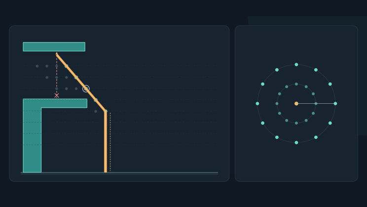
Side view: the straight way down is blocked. Grey candidates are dropped, teal ones kept, and the outermost route (ringed) is kept on purpose until it clears the ledge. Top view: the 25 places tried from each route, every layer
Where trees don't fit
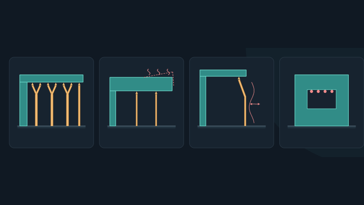
A big flat underside, a heavy hot overhang, a tall slender branch and a sealed cavity
- Big flat undersides. They need many tips, and trees leave a worse underside there. Even consumer slicers switch to a normal grid under large flat overhangs [3]. In metal, a fixture, a wall or a plate is usually the better tool.
- Heavy or hot overhangs. Thin tips carry and conduct less. Supports also hold the part against distortion and take heat away [7], and less support volume can mean more distortion: in powder-bed fusion, tree-like supports show a clear trade-off between support volume and part displacement [18].
- Tall, slender branches. Sparse trees can be unstable and hard to print [19]. In wire-arc deposition a thin branch is a point-by-point bar, about 8 mm thick, built with pauses of 33 to 75 seconds per droplet in one study [20], and WAAM design rules warn that long, thin, unsupported members are difficult to deposit [21]. Bead width sets the thinnest branch; the process sets the steepest lean.
- No way out. A sealed cavity can't be supported from the plate by anything, tree or not. Branches only go down, so the generator marks such tips as unreachable instead of pretending.
- Six axes. If the part or the torch can be tilted, the best support may be none at all.
Try it
The generator runs as an extension for ENCY 3. ENCY now has an extension store, so trying it on your own part takes one click: "Install in ENCY" on its page.
Bonus, for those who read this far: the part that wanted to be a ballerina
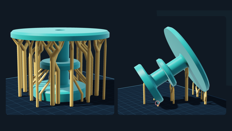
Left: 68 contacts and a forest of 256 branches. Tilted 59°: 17 contacts under the lower rims, 43 branches, and a part balancing on one edge
Before growing a forest, it's worth asking whether a rotation removes the overhang, so the extension also searches build orientations. It checks 84 near-uniform directions on a golden-angle sphere lattice [22], plus the part's big flat faces and the main axes.
On the demo part I asked for minimum supports. It tried 112 directions and found a 59° tilt. That took the part from 68 contacts to 17, from a forest of 256 branches to 43: 90% less support. The faces are now steep enough, so what's left holds the lower rims of the cap, the collar and the flange. The part loved it. It rose onto one edge of its flange, like a ballerina on pointe.
For arc deposition that is a terrible first layer: a tiny contact area, a poor path for the heat, and good luck clamping it. WAAM orientation research deliberately maximises first-layer area [23]. So the search gives a ranking, not a decision. The columns learned to dance; the part wanted to be a ballerina; the engineer still chooses the music.
References
- UltiMaker Cura 5.4.0 release notes: the new tree support contributed by Thomas Rahm, 2023. https://github.com/Ultimaker/Cura/releases/tag/5.4.0
- Prusa Research. PrusaSlicer 2.6 is here: organic supports, 2023. https://blog.prusa3d.com/prusaslicer-2-6-is-here-organic-supports-text-embossing-new-cut-tool-and-more_79322/
- Bambu Lab Wiki. Support (tree hybrid style). https://wiki.bambulab.com/en/software/bambu-studio/support
- R. Schmidt, N. Umetani. Branching Support Structures for 3D Printing. ACM SIGGRAPH 2014 Studio. https://doi.org/10.1145/2619195.2656293
- Materialise. Materialise Introduces New Release of Magics: Feel the Power of Improved Efficiency with Magics 19 (new Tree Supports module), press release, 21 October 2014. https://www.materialise.com/en/news/press-releases/magics-improved-efficiency
- B. Yun, K.-Y. Lee, K.-Y. Shin, D.-S. Shim. Enabling overhang fabrication in directed energy deposition using removable supports: Thermal behavior and down-skin surface formation. Journal of Materials Research and Technology 42, 8270–8288, 2026. https://doi.org/10.1016/j.jmrt.2026.05.101
- K. Bartsch, C. Emmelmann. Enabling Cost-Based Support Structure Optimization in Laser Powder Bed Fusion of Metals. JOM 74(3), 1126–1135, 2022. https://doi.org/10.1007/s11837-021-05055-5
- J. L. McNeil, J. J. Penney, M. Lamsey et al. Extending wire-arc directed energy deposition using non-gravity aligned (NGA) torch methods. Journal of Manufacturing Processes 152, 139–153, 2025. https://doi.org/10.1016/j.jmapro.2025.07.062
- L. D. Evjemo, G. Langelandsvik, S. Moe, M. H. Danielsen, J. T. Gravdahl. Wire-arc additive manufacturing of structures with overhang: Experimental results depositing material onto fixed substrate. CIRP Journal of Manufacturing Science and Technology 38, 186–203, 2022. https://doi.org/10.1016/j.cirpj.2022.04.006
- C. Dai, C. C. L. Wang, C. Wu, S. Lefebvre, G. Fang, Y.-J. Liu. Support-free volume printing by multi-axis motion. ACM Transactions on Graphics 37(4), 2018. https://doi.org/10.1145/3197517.3201342
- T. Zhang, G. Fang, Y. Huang, N. Dutta, S. Lefebvre, Z. M. Kilic, C. C. L. Wang. S³-Slicer: A General Slicing Framework for Multi-Axis 3D Printing. ACM Transactions on Graphics 41(6), 2022. https://doi.org/10.1145/3550454.3555516
- C. Greer, A. Nycz, M. Noakes, B. Richardson, B. Post, T. Kurfess, L. Love. Introduction to the design rules for Metal Big Area Additive Manufacturing. Additive Manufacturing 27, 159–166, 2019. https://doi.org/10.1016/j.addma.2019.02.016
- L. Yuan, Z. Pan, D. Ding, Z. Yu, S. van Duin, H. Li, W. Li, J. Norrish. Fabrication of metallic parts with overhanging structures using the robotic wire arc additive manufacturing. Journal of Manufacturing Processes 63, 24–34, 2021. https://doi.org/10.1016/j.jmapro.2020.03.018
- P. Gradl, A. Cervone, P. Colonna. Influence of build angles on thin-wall geometry and surface texture in laser powder directed energy deposition. Materials & Design 234, 112352, 2023. https://doi.org/10.1016/j.matdes.2023.112352
- C. Eloy. Leonardo's rule, self-similarity, and wind-induced stresses in trees. Physical Review Letters 107, 258101, 2011. https://doi.org/10.1103/PhysRevLett.107.258101
- C. D. Murray. The physiological principle of minimum work. PNAS 12(3), 207–214, 1926. https://doi.org/10.1073/pnas.12.3.207
- J. Vanek, J. A. Garcia Galicia, B. Benes. Clever Support: Efficient Support Structure Generation for Digital Fabrication. Computer Graphics Forum 33(5), 117–125, 2014. https://doi.org/10.1111/cgf.12437
- S. Weber, J. Montero, M. Bleckmann, K. Paetzold. Parametric design optimisation of tree-like support structure for the laser-based powder bed fusion of metals. Journal of Manufacturing Processes 84, 660–668, 2022. https://doi.org/10.1016/j.jmapro.2022.09.063
- J. Dumas, J. Hergel, S. Lefebvre. Bridging the Gap: Automated Steady Scaffoldings for 3D Printing. ACM Transactions on Graphics 33(4), 2014. https://doi.org/10.1145/2601097.2601153
- V.-A. Silvestru, I. Ariza, J. Vienne et al. Performance under tensile loading of point-by-point wire and arc additively manufactured steel bars for structural components. Materials & Design 205, 109740, 2021. https://doi.org/10.1016/j.matdes.2021.109740
- H. Lockett, J. Ding, S. Williams, F. Martina. Design for Wire + Arc Additive Manufacture: design rules and build orientation selection. Journal of Engineering Design 28(7–9), 568–598, 2017. https://doi.org/10.1080/09544828.2017.1365826
- Á. González. Measurement of Areas on a Sphere Using Fibonacci and Latitude–Longitude Lattices. Mathematical Geosciences 42, 49–64, 2010. https://doi.org/10.1007/s11004-009-9257-x
- Y. Alomari, M. T. Birosz, M. Andó. Part orientation optimization for Wire and Arc Additive Manufacturing process for convex and non-convex shapes. Scientific Reports 13, 2203, 2023. https://doi.org/10.1038/s41598-023-29272-x
