How to Define the Tool Center Point (TCP) on a Robot
Categories: Blog

TCP is the reference point for motion planning, path execution, and accurate task completion. A misconfigured TCP can lead to misaligned welds, faulty assemblies, or even collisions. That’s why understanding and correctly calibrating the TCP is critical for robotic performance, accuracy, and repeatability.
⚠️ Safety Note: A misconfigured TCP can also be dangerous — always verify the TCP before running automated motions.
Basic Principles of TCP
At its core, TCP is a coordinate defined relative to the robot’s tool flange. It tells the robot where the “business end” of the tool is, typically defined in X, Y, Z (position) and Rx, Ry, Rz (orientation). Note that some systems may represent orientation differently — for example, using quaternions or axis-angle formats depending on the robot controller.
The TCP is defined by a position and orientation offset from the robot’s flange, often represented as a transformation matrix. When planning a path or executing a motion, the robot uses inverse kinematics to ensure the tool tip follows the correct trajectory, based on the defined TCP. A miscalculated TCP means the robot’s real-world tool position will differ from the programmed path.
In Cartesian programming, where each motion command defines a target in space, the accuracy of the TCP directly influences the robot’s ability to reach the right location. This makes TCP especially important when switching between different end effectors.
Calibrating the TCP: Step-by-Step
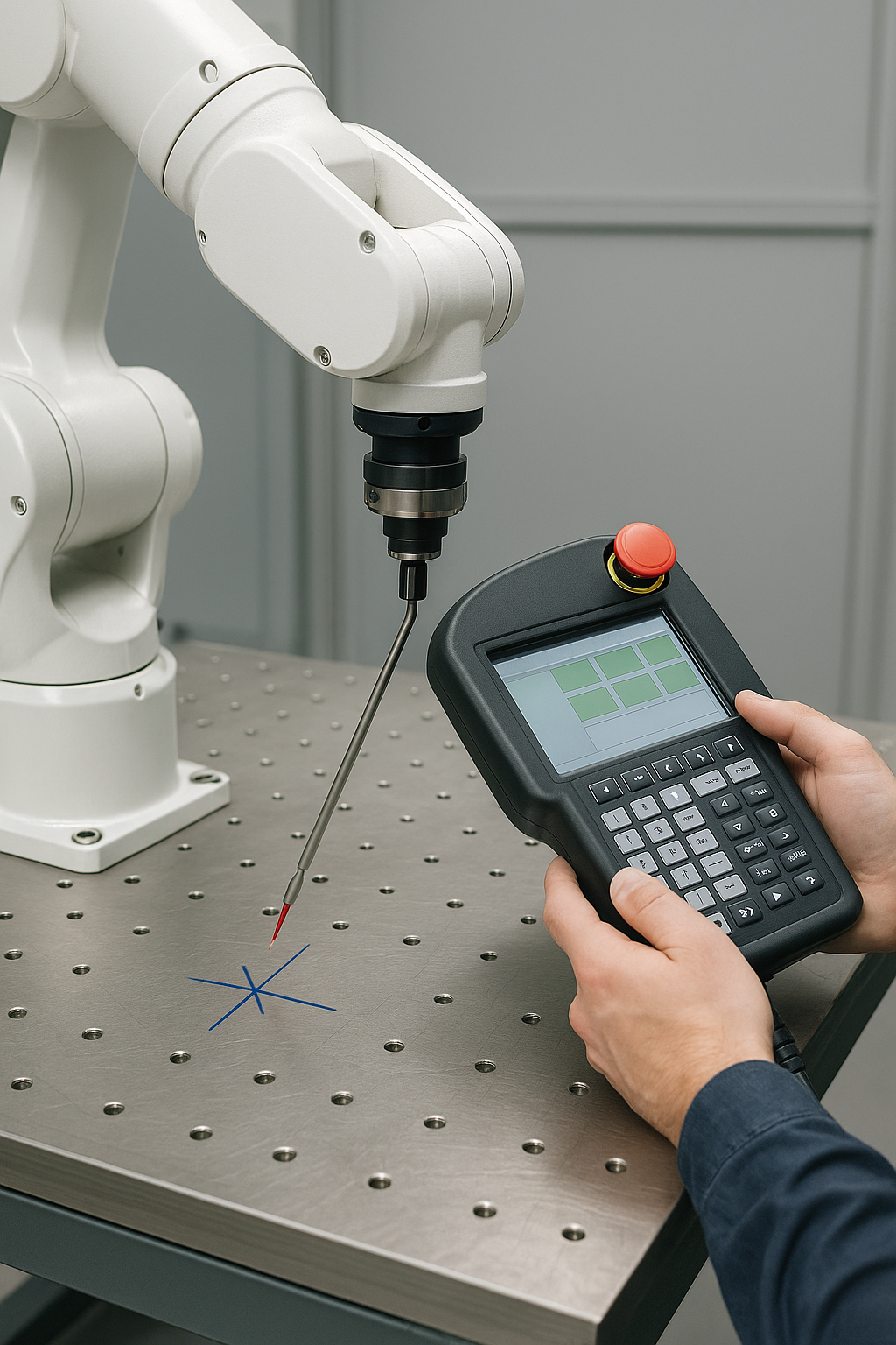
There are several common methods for TCP calibration, depending on tool type, required precision, and available equipment. Here’s a reliable step-by-step method using the “Four-Point Method,” which requires minimal equipment:
Securely attach the tool to the robot flange. Then define a sharp object or physical marker in the work cell — this will serve as your fixed reference point. Move the tool so that the same point on the tool touches the fixed reference from at least four different arm positions. At each position, record the robot’s flange coordinate values. Then calculate the TCP offset using either robot software or geometric methods. Some advanced systems automate this process using calibration fixtures or laser sensors, significantly reducing human error.
For example, in a welding application, the tip of the welding tool must be precisely measured and set as the TCP. Even a 1 mm shift can result in welds that miss their seam, especially in tight tolerances.
Accuracy Check and Tolerance Table
After calibration, it’s crucial to verify TCP accuracy. Methods include using dial indicators, laser trackers, or simply repeating the 4-point check to assess variation.
Note: The acceptable deviation depends heavily on the application requirements. Values below are typical guidelines and should be validated against process specifications.
Acceptable TCP Error by Application
| Application | Acceptable TCP Deviation (mm) |
|---|---|
| Spot Welding | < 0.5 – 1.0 |
| Arc Welding | < 0.5 |
| Assembly (Standard) | < 0.2 |
| Precision Assembly | < 0.05 |
| Laser Cutting / Drilling | < 0.01 |
Common Mistakes and How to Fix Them
Many TCP-related issues stem from small oversights. Loose or wobbly tool mounting is a common issue — always double-check tightness. Using the wrong reference point during calibration can introduce consistent errors, so ensure consistency. Inconsistent calibration angles may also degrade precision; try to use symmetrical poses for better geometric results. Finally, if you’re manually entering flange values, double-check units and sign conventions to avoid miscalculations.
Users should also make sure the orientation of the tool matches documentation defaults. If your robot’s configuration uses a default TCP pointing in a certain direction (e.g., Z+), make sure the real tool aligns with that orientation. Misalignment here can lead to rotational errors that are difficult to diagnose later.
Maintaining TCP Accuracy
TCP isn’t a “set it and forget it” setting. It can drift over time due to tool wear or replacement, flange deformation after a collision, thermal expansion, or changes made by operators. To maintain accuracy, high-precision tools should be recalibrated weekly or monthly. Develop a checklist-based routine for daily pre-run TCP verification, and use automated diagnostic routines if your robot controller supports them.
Before every shift, confirm that the tool is securely mounted and that your reference object is present and correctly placed. Check whether the TCP appears consistent across repeated motions. Log the date of the last successful calibration, and always recalibrate after tool changes or unexpected impacts. Consistent logging and procedural discipline help ensure lasting precision.
You can also define backup TCP configurations for tools that are exchanged frequently. This allows fast recovery and consistent performance across different applications and robot programs.
Understanding the Math: TCP by Geometry
Let’s say your tool tip or end-effector reference point is 100 mm along the Z-axis and 30 mm along the X-axis from the center of the flange. The TCP offset in tool coordinates is then:
- X: 30 mm
- Y: 0 mm
- Z: 100 mm
- Rx, Ry, Rz: 0° (assuming no rotation relative to flange)
The transformation matrix combines this offset with the flange pose to calculate global tool position. Most robot programming environments allow this to be input manually or calculated using built-in routines. Each value entered must match the physical tool setup to ensure accurate Cartesian positioning.
Comparing Calibration Methods
Let’s compare the most common methods for TCP calibration.
| Method | Accuracy | Equipment Needed | Time Required | Notes |
|---|---|---|---|---|
| 4-Point Method | Medium | None (manual) | ~10 minutes | Most common, good for general use |
| Dial Indicator Method | High | Dial gauge | ~15 minutes | Great for symmetric tools |
| Laser Tracker Method | Very High | Laser tracker system | ~30+ minutes | High precision, costly |
| Automated Tool | High to Very High | Calibration fixture/tool | ~5–10 minutes | Fast and accurate, vendor-dependent |
TCP for Different Tool Types
Not all tools are created equal. Some tips:
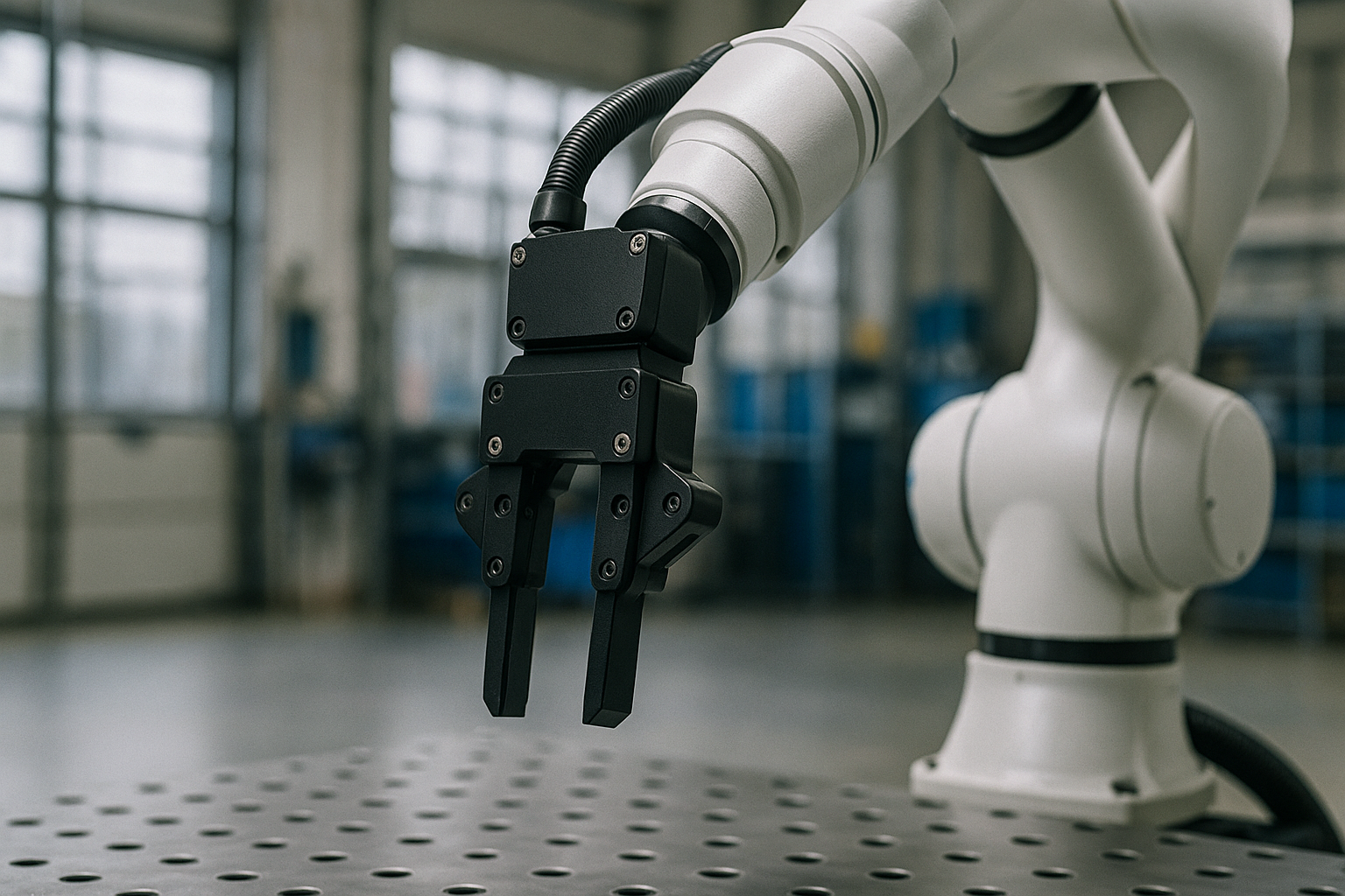
- Symmetric tools (e.g., weld torches): Easier to calibrate with the 4-point method.
- Asymmetric tools (e.g., grippers): May require dynamic calibration using vision or external measurement systems.
- Rotary tools: Need to define orientation carefully due to tool spin.
- Exchangeable tools: Use tool changers with stored TCP presets to avoid recalibration.
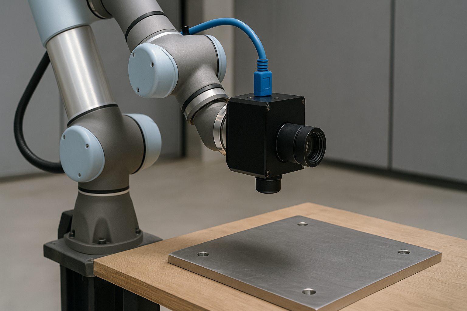
An image-based tool detection system can support these calibrations by identifying tool type and calculating the tool center point automatically. This approach is becoming more common in high-mix robotic cells.
Decision Flowchart: How to Choose a TCP Method
Choosing the appropriate method for defining the Tool Center Point (TCP) depends on several key factors: the tool’s geometry, required precision, and equipment availability. Here’s how to decide:
1. Is the tool symmetric?
- Yes → Use the 4-point method or a dial indicator. These methods work well for tools with a central tip (e.g., weld torches, pens).
- No → Continue to next question.
2. Does the application require high precision?
- Yes → Use a laser tracker or automated calibration fixture. Ideal for laser cutting or fine assembly.
- No → Continue to next question.
3. Do you use an automatic tool changer (ATC)?
- Yes → If supported, load a stored TCP preset for that tool.
- No → Use the 4-point method or another manual technique.
Conclusion
Correctly defining and calibrating the Tool Center Point is fundamental to robotic accuracy and performance. Whether you’re welding, assembling, or machining, TCP is at the heart of the robot’s effectiveness. A well-maintained TCP ensures consistency, quality, and uptime across your operations. Understanding the theory — and practicing the techniques — puts you in control of robotic precision.
The robot’s ability to move in the exact direction and reach the target point relies on how well the TCP was set up. Defining the tool center point isn’t just a setup step — it’s the start of every successful robot task.
