Metal Additive Manufacturing: Building the Future One Layer at a Time
Categories: Blog
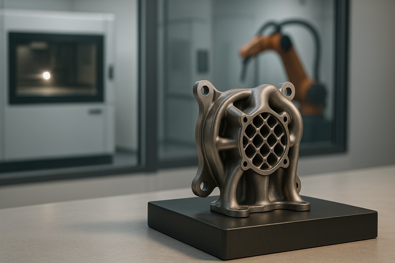
Imagine designing a part whose interior is a network of cooling channels and whose exterior is a sweep of seamless, curvature‑continuous geometry. Now imagine building it directly from metal powder or wire, without carving, welding, or assembly. That’s the promise of metal additive manufacturing (MAM), and it’s transforming how we think about making things.
Unlike traditional machining, which starts with a block and cuts away, MAM adds material only where it’s needed. The result is less waste, greater design freedom, and new possibilities for performance. This shift fits a broader move toward agile, sustainable, digitally connected production. Metal AM lets engineers realize complex geometries, internal structures, and lightweight forms that are impossible — or prohibitively costly — using subtractive methods.
Glossary: Quick Guide to Terms
- Additive Manufacturing (AM) — Producing parts by adding material layer by layer from a digital model.
- Metal Additive Manufacturing (MAM) — AM processes specifically for metal parts and feedstocks.
- Design for Additive Manufacturing (DfAM) — Methods and guidelines to design parts that leverage AM (consolidation, lattices, internal channels) while respecting process constraints.
- Powder Bed Fusion (PBF) — Family of processes that melt metal powder in a powder bed to build parts. Includes PBF‑LB/M and PBF‑EB/M.
- PBF‑LB/M (Laser Powder Bed Fusion, LPBF) — Laser‑based melting of metal powder to build dense, accurate parts.
Also known as: SLM, DMLS (vendor/legacy terms for LPBF). - PBF‑EB/M (Electron Beam Powder Bed Fusion, EB‑PBF) — Electron beam melting in vacuum; well suited to reactive alloys (e.g., titanium) and certain controlled‑porosity structures.
Also known as: EBM (legacy/vendor term). - Directed Energy Deposition (DED) — Feeding wire or powder into a melt pool created by a focused energy source (laser, arc, or electron beam) to deposit material bead by bead.
- WAAM (Wire Arc Additive Manufacturing) — Arc‑based DED using wire feedstock; ideal for large near‑net‑shape structures and repairs at high deposition rates.
- Binder Jetting (BJT) — Inkjet‑style deposition of a binder onto a metal powder bed to form a “green” part, followed by debinding and high‑temperature sintering to densify; design must allow for predictable shrinkage.
- Metal Material Extrusion (metal FFF / BMD) — Printing a metal‑filled polymer filament to make a green part that then undergoes debinding and sintering to become fully metallic.
Also called: bound metal or metal FFF (BMD is a vendor term). - Cold Spray — Solid‑state deposition: metal particles accelerated to supersonic speeds bond on impact without melting; used for coatings and dimensional restoration with minimal oxidation and heat input.
- Debinding & Sintering (D&S) — Furnace steps used in BJT and metal FFF to remove binder and achieve density; introduces predictable shrinkage that must be considered in design.
- Hot Isostatic Pressing (HIP) — High‑pressure, high‑temperature process that closes internal pores and improves fatigue properties; common for LPBF parts.
- STL File — Triangle‑mesh format widely used for 3D printing; encodes geometry only (no units/materials), originally tied to stereolithography.
- In‑Situ Monitoring — On‑machine sensing (optical/thermal proxies and layer imaging) used to detect build anomalies during printing.
- Selective Laser Sintering (SLS) — Commonly refers to polymer powder‑bed printing; do not use for metals. For metal powder‑bed processes use LPBF (PBF‑LB/M) or EB‑PBF (PBF‑EB/M).
From Lasers to Binders: How It All Works
Not all metal 3D printing is the same. In one lab you might watch a high‑power laser sweep across a bed of fine powder; in another, an inkjet‑style head lays down tiny droplets of binder that later transform in a furnace. Elsewhere, a robot feeds metal wire into an electric arc to build up large components, or a nozzle drives cold metal particles to supersonic speeds so they bond without ever melting. All of these approaches live under the metal additive manufacturing umbrella, but each brings its own physics, trade‑offs, and sweet spots.
Laser Powder Bed Fusion — formally PBF‑LB/M and often called LPBF — melts powder layer by layer to produce dense, highly accurate parts and is a mainstay in aerospace and medical work. Its counterpart, Electron Beam PBF (PBF‑EB/M or EB‑PBF), does the same in vacuum with an electron beam, which suits reactive alloys like titanium and enables certain controlled‑porosity structures. Binder Jetting (BJT) prints at room temperature by selectively depositing a liquid binder; the “green” part is then debound and sintered at high temperature to reach final density, trading laser‑induced residual stresses for predictable shrinkage that must be designed for. Directed Energy Deposition (DED) adds material into a melt pool on a surface or in free space: with powder or wire and a laser it excels at cladding, feature addition, and repairs; with an electric arc — often referred to as WAAM, an arc‑based form of DED — it achieves very high deposition rates for large near‑net‑shape structures. Metal Material Extrusion (metal FFF/BMD) prints a metal‑filled filament to form a green part that also requires debinding and sintering, offering a lower‑cost path for prototypes and fixtures. Finally, Cold Spray is a solid‑state route: particles hit the substrate at supersonic speed and bond without melting, enabling rapid coatings and restorations with minimal oxidation and heat input.
Because these methods differ in precision, build rate, thermal history, material efficiency, and downstream steps, process selection is about matching the physics to the problem — LPBF or EB‑PBF for intricate, high‑performance components; DED (including WAAM) for large sections and repairs; BJT and metal FFF/BMD for throughput and cost‑sensitive parts that tolerate sintering‑driven shrinkage; and Cold Spray when you need bonding without melting. Taken together, this toolkit is what makes metal AM so versatile — and so powerful — across industries.
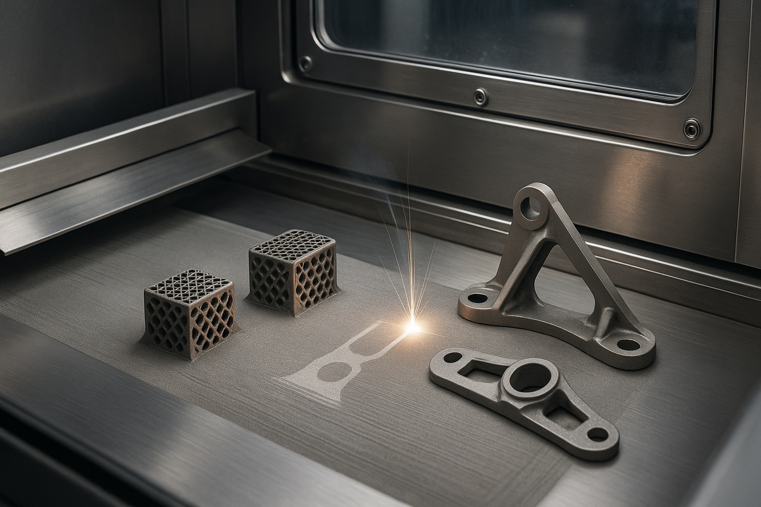
Powder Bed Fusion (PBF)
Process. A thin layer of metal powder is spread and selectively melted to build parts layer by layer.
Common methods.
- PBF‑LB/M (LPBF/SLM/DMLS): Laser melting of powder to produce dense, high‑precision parts.
- PBF‑EB/M (EB‑PBF/EBM): Electron beam melting in vacuum, well suited to titanium and porous implant structures.
Best for.
- High‑precision metal parts with complex internal channels and lattices.
- Medical implants and aerospace components requiring tight tolerances and repeatable properties.
Notes on post‑processing.
Expect support removal, plate separation, stress‑relief heat treatment, and — when required — HIP and machining to meet final tolerances and fatigue requirements.
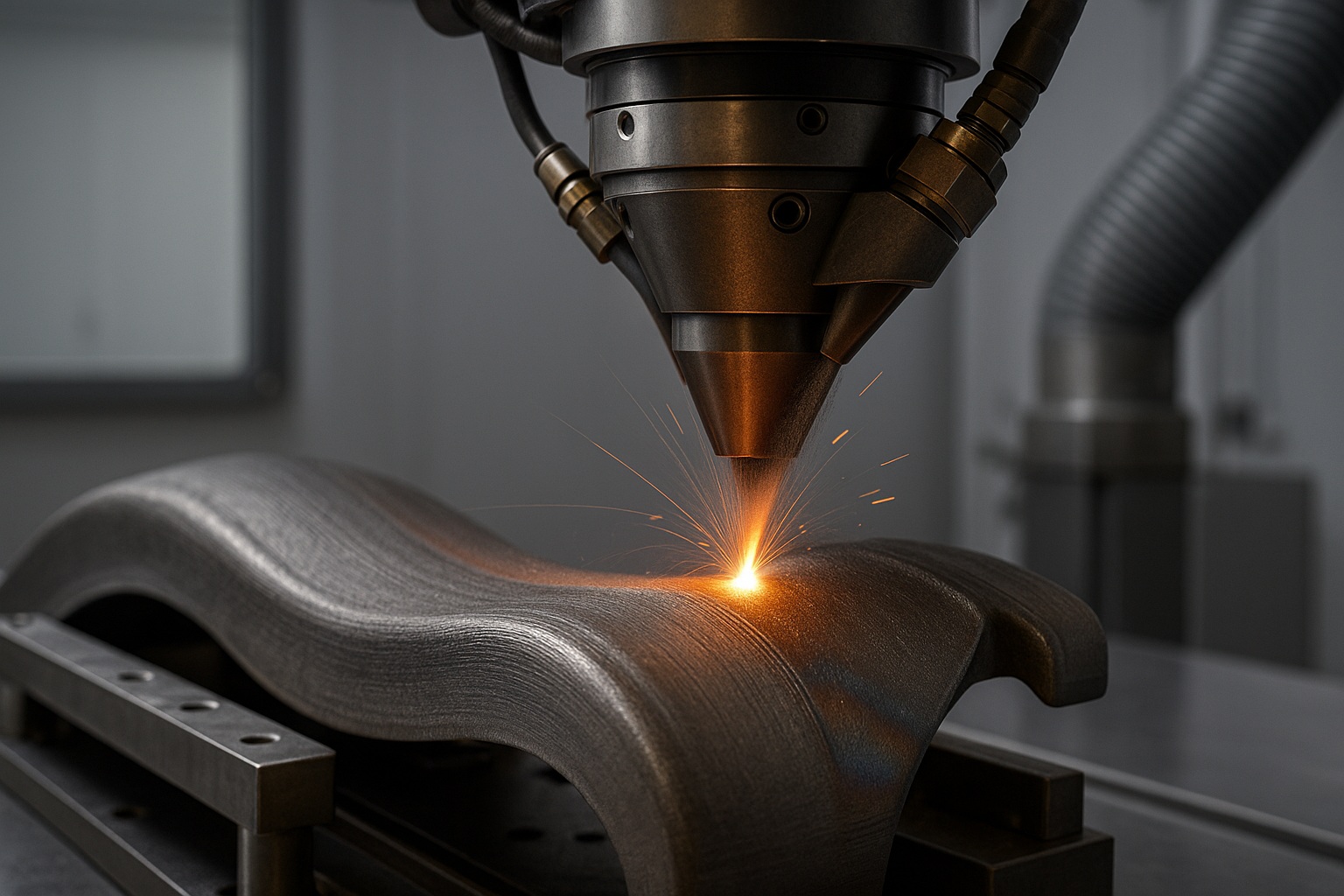
Directed Energy Deposition (DED)
Process. Metal wire or powder is fed into a melt pool created by a focused energy source (laser, electric arc, or electron beam) and deposited bead‑by‑bead.
Common methods.
- Laser DED (powder or wire): High‑accuracy feature addition, cladding, and repairs.
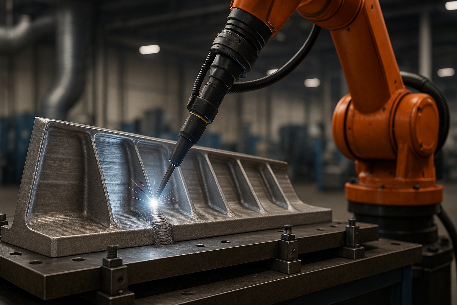
- Arc‑based DED (Wire Arc Additive Manufacturing, WAAM): Electric‑arc process with wire feed; very high deposition rates for large structures.
- Electron‑beam or plasma variants: For specific environments or rates.
Best for.
- Repairing and restoring worn components (e.g., turbine blades).
- Hybrid manufacturing (combining additive and subtractive).
- Large‑scale metal deposition with wire; localized additions and cladding with powder.
Notes on material efficiency.
Wire‑based DED/WAAM approaches near‑100% feedstock utilization; powder‑based DED can have lower capture efficiency depending on parameters. Typical post‑processing includes heat treatment and machining.
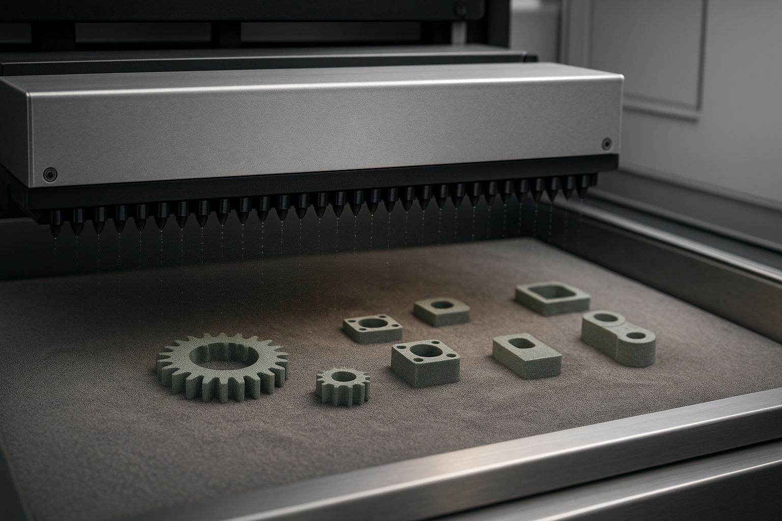
Binder Jetting (BJT)
Process. A binder is selectively jetted onto a metal powder bed layer by layer to form a “green” part, followed by debinding and high‑temperature sintering to densify.
Best for.
- Cost‑effective series production of metal parts.
- Complex geometries with careful allowance for shrinkage and sintering fixtures (setters).
Notes.
Printing occurs at room temperature (low thermal stress during printing), but the furnace steps drive densification and can introduce shape change that must be compensated in design.
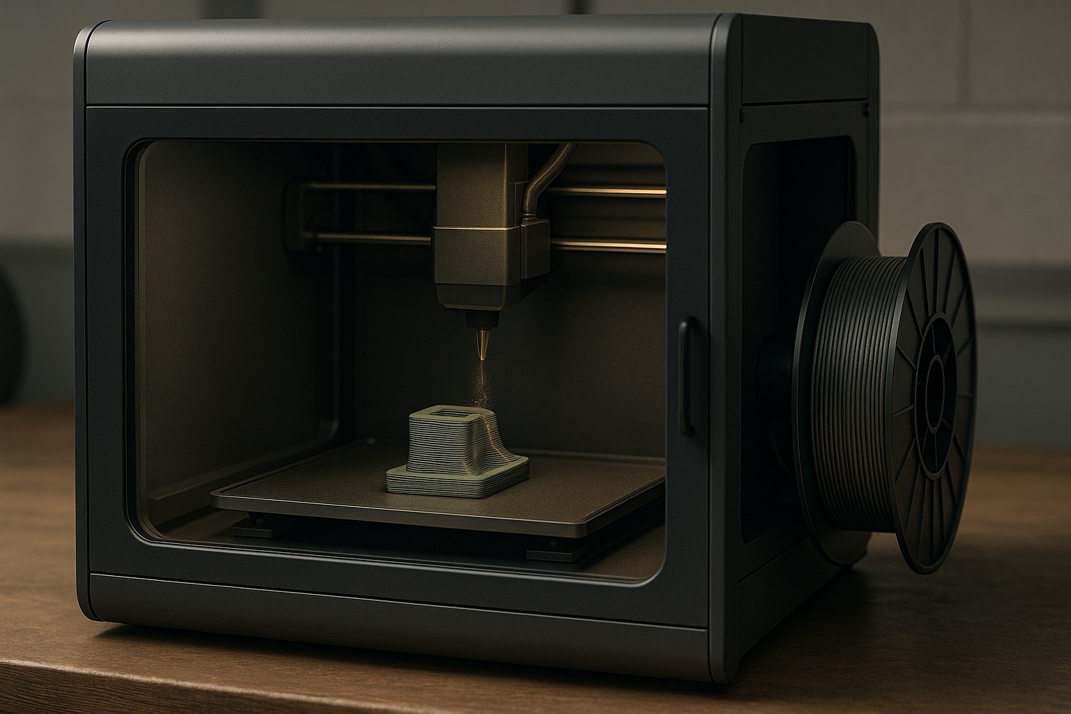
Metal Material Extrusion (Metal FFF/BMD)
Process. A metal‑filled polymer filament is extruded like FFF to form a green part, then debound and sintered to fuse the metal.
Best for.
- Rapid prototyping of metal parts before high‑cost production.
- Lower‑cost entry into metal AM for jigs, fixtures, and R&D.
Notes on infrastructure.
Although printing can be done on modified/qualified FFF systems, debinding and sintering equipment (or an external service) is required to reach final properties and density.
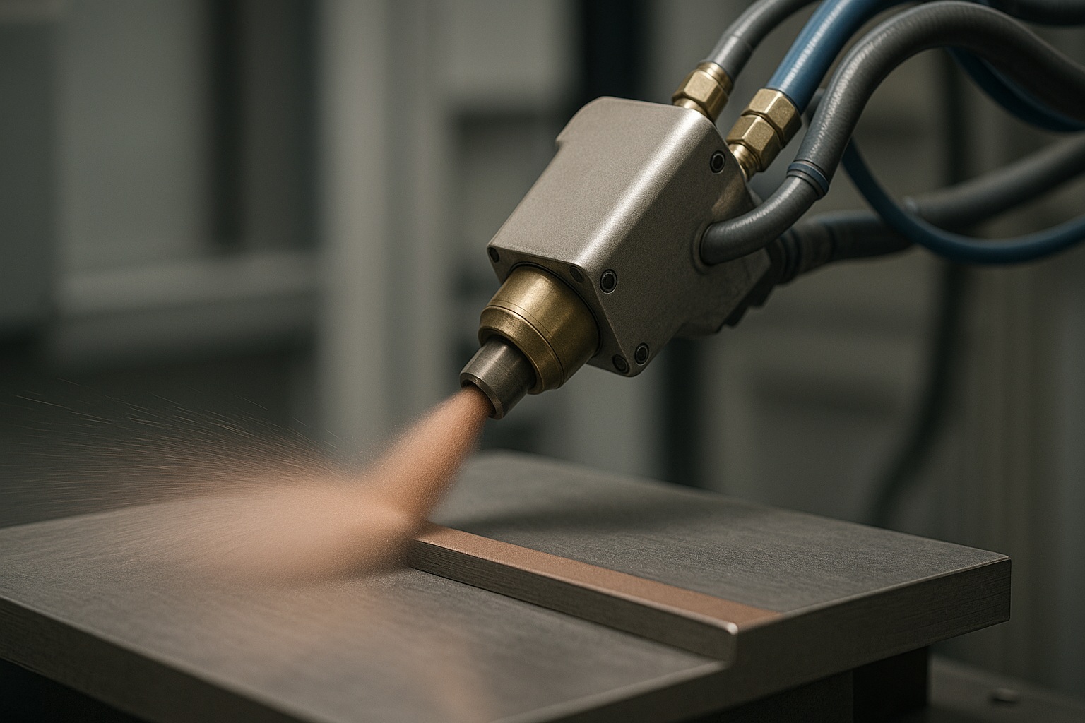
Cold Spray
Process. Solid metal particles are accelerated to supersonic speeds and impact‑bond to the substrate without melting.
Best for.
- Coatings, dimensional restoration, and oxidation‑sensitive materials
- Very high deposition rates with minimal heat‑affected zone.
Notes.
Often followed by machining to final size; heat treatment may be used to optimize bonding and properties.
Comparison of Technologies
While the story of metal additive manufacturing is filled with nuance and context, sometimes a snapshot can help clarify things. Here’s a concise comparison of the five key technologies shaping the field:
| Technology | Material Form | Energy / Mechanism | Best For | Typical Notes |
|---|---|---|---|---|
| PBF‑LB/M (LPBF) | Powder | Laser melting in a powder bed | Dense, high‑precision parts; complex internal channels; aerospace & medical | Requires support removal, stress‑relief; often HIP; machining as needed |
| PBF‑EB/M (EB‑PBF) | Powder | Electron beam melting in vacuum | Titanium alloys; porous implants; reduced residual stress via elevated build temps | Powder removal; stress‑relief; machining as needed |
| DED – Laser (powder/wire) | Powder or wire | Laser melt pool with blown powder or wire feed | Repairs, cladding, feature addition; medium‑to‑large parts | Heat treatment; machining to tolerance; powder capture varies |
| DED – Arc (WAAM) | Wire | Electric arc + wire feed | Large structures; near‑net‑shape preforms; high deposition rates | Heat treatment; substantial machining to final geometry |
| Binder Jetting (BJT) | Powder | Binder deposition → debinding + sintering | High‑throughput series parts; cost‑sensitive applications | Predictable shrinkage; setters/fixturing; optional infiltration/sizing |
| Metal Material Extrusion (metal FFF / BMD) | Filament | Extrusion of metal‑filled filament → debinding + sintering | Prototyping and lower‑cost metal parts; educational/R&D | Densification via D&S; machining as needed |
| Cold Spray | Powder | Solid‑state supersonic particle impact (no melting) | Coatings and repairs; oxidation‑sensitive materials | Minimal heat input; post‑machining common; optional heat treatment |
Designing for a New Kind of Manufacturing
Designing for metal additive manufacturing is not a simple case of taking an existing CAD model and hitting ‘print.’ The process begins with rethinking how a part is structured and optimized — not only to be printable but to take full advantage of the capabilities that additive manufacturing brings.
One of the most powerful tools in this design phase is topology optimization. By simulating loads, stresses, and boundary conditions, engineers can automatically generate geometry that removes material where it’s not structurally necessary. This leads to lightweight yet durable forms that are almost impossible to create using traditional methods. These geometries often resemble natural bone structures — thin struts, hollow sections, and lattice cores.
Design for Additive Manufacturing (DfAM) principles encourage engineers to think differently. For instance, instead of designing multiple components to be assembled later, DfAM favors consolidated designs — multiple functions combined into a single part. This not only reduces manufacturing time but also removes potential failure points.
However, many technical considerations come into play:
- Support structure design: Minimizing support reduces post-processing and material waste.
- Build orientation: Impacts strength, surface finish, and build time.
- Layer thickness and resolution: Affects detail, accuracy, and cost.
- Thermal distortion: Needs to be predicted and compensated through simulation.
These complexities are managed through specialized additive software that integrates with CAD platforms. Programs like Siemens NX, nTopology, and Autodesk Netfabb provide dedicated toolsets for additive modeling, simulation, and slicing, making it easier to go from idea to production-ready geometry.
Supports are added where needed. The model is sliced into thousands of layers. Every decision, from build orientation to wall thickness, impacts cost, quality, and print success. These steps are essential in ensuring that the additive workflow delivers a reliable and functional final part.
Materials, Post-Processing, and the Role of Steel
The performance of a metal additive part is intrinsically linked to the material used — and here, the selection is broader and more advanced than ever. The range includes:
- Stainless Steels (e.g., 316L, 17-4PH): Corrosion resistance, strength, and widespread industrial acceptance.
- Titanium Alloys (e.g., Ti-6Al-4V): Lightweight and strong, especially in aerospace and biomedical fields.
- Aluminum Alloys (e.g., AlSi10Mg): Excellent thermal properties, ideal for automotive and aerospace cooling components.
- Nickel Superalloys (e.g., Inconel 718, 625): High heat and oxidation resistance, critical for turbine and engine components.
- Cobalt-Chrome, Copper, Tool Steels, Refractory Metals: Used in medical, electrical, and tooling applications.
In particular, additive manufacturing steel has grown from basic stainless grades to more advanced tool and structural steels. These developments expand the technology into die/mold manufacturing, energy, and structural components.
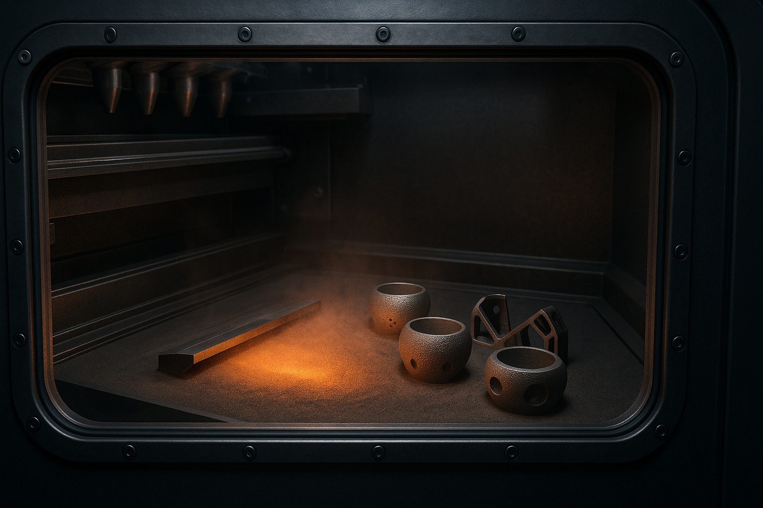
But even the best-printed part is incomplete without post-processing. This stage is essential to relieve residual stresses, achieve mechanical properties, and bring parts within tolerance:
- Stress relief and thermal treatments tailored to each alloy.
- HIP (Hot Isostatic Pressing) to close internal pores and enhance fatigue resistance.
- Machining or grinding to meet tight dimensional and surface finish specifications.
- Shot peening or polishing to improve fatigue life and visual appearance.
- Chemical etching or coating where corrosion resistance or biocompatibility is critical.
Post-processing is where the promise of 3D-printed metal becomes real-world functionality.
Quality Control and Inspection
In high-performance sectors like aerospace, energy, and medical, every part must meet strict quality criteria. Metal additive manufacturing enables unprecedented geometric freedom — but that must be matched by robust inspection and validation systems.
Quality control begins during the print itself. Most modern MAM systems are equipped with in-situ monitoring tools that track laser or beam power, melt pool temperature, layer consistency, and environmental conditions in real time. These systems can detect anomalies — such as spatter, recoater errors, or local overheating — while the part is still being built.
Once the part is complete, a range of traditional and advanced inspections follows:
- Nondestructive Testing (NDT): X-ray and computed tomography (CT) scans are used to inspect internal structures, revealing porosity, cracks, or inclusions.
- Ultrasonic Testing: Useful for dense components, especially large parts produced via DED.
- Mechanical Testing: Tensile and fatigue tests ensure the part can withstand its intended operational environment.
- Microstructural Analysis: Using SEM, EDS, and metallography to confirm grain structure, phase distribution, and alloy consistency.
- Coordinate Measuring Machines (CMM): Used to verify that printed parts match CAD geometry within acceptable tolerances.
All these inspections help ensure that 3D printed parts are not only functional but meet or exceed the standards expected from traditionally manufactured components.
Economic Considerations and Business Case
It’s true that metal additive manufacturing isn’t cheap — yet. The cost of industrial machines, specialty powders, and skilled labor is significant. But as with any disruptive technology, the value lies not in replacing traditional methods, but in enabling what was previously impossible.
Where MAM shines economically:
- High-complexity, low-volume production: Traditional tooling costs make low-run parts expensive. MAM eliminates tooling and enables agile, just-in-time manufacturing.
- Weight-sensitive applications: In aerospace, each gram saved is money saved. AM’s ability to hollow parts and reduce mass is a direct cost benefit.
- Spare part digitalization: Instead of warehousing components, digital files can be printed on demand anywhere in the world.
- Productivity gains: Reduced assembly steps, integrated functionality, and fewer parts to manage.
Return on investment can be achieved more quickly than many assume — especially in sectors where performance improvements (e.g., improved cooling, lighter assemblies, or patient-specific implants) are highly valued.
Barriers that remain:
- High material costs (especially certified metal powders).
- Need for operator training and process qualification.
- Limited scalability for large parts or very high production volumes.
Nonetheless, companies increasingly adopt hybrid models: using AM where it offers value, while keeping subtractive methods where they’re most efficient.
At first glance, metal AM can seem prohibitively expensive. The machines, powders, and post-processing tools are costly, and the learning curve is steep. But for the right application, the return on investment is substantial.
MAM is ideal for low-volume, high-complexity parts. It reduces assembly steps, shortens lead times, and eliminates the need for custom tooling. Spare parts can be printed on demand, minimizing inventory and logistics costs. In industries like aerospace and healthcare, the value of performance, weight reduction, and custom geometry outweighs initial capital costs.
Moreover, digital workflows enable decentralized manufacturing — where the same part can be printed anywhere with a certified file and machine. This has significant implications for supply chains and production agility.
Standards, Certification, and Industry Adoption
For metal AM to gain widespread adoption in critical applications, standards and certifications are non-negotiable. These frameworks define how parts are designed, produced, tested, and qualified. Without them, manufacturers cannot prove repeatability or meet safety requirements.
Key frameworks include:
- ASTM International F42 Committee: Standards for materials, processes, testing methods, and terminology.
- ISO/ASTM 52900 Series: Covers general principles, design, and quality assurance.
- AS9100 (aerospace) and ISO 13485 (medical): Adapted quality management systems for regulated industries.
- FDA Guidance: For biocompatibility, traceability, and validation in patient-specific medical parts.
Process qualification is a cornerstone of certification. It includes validating material properties, process stability, machine calibration, and part performance over repeated builds. As part of this, manufacturers often use closed-loop quality systems and documentation that span the entire digital workflow — from CAD to final part testing.
Industry adoption is growing across aerospace, defense, oil and gas, energy, and medical sectors — driven by increasing trust in these standardization efforts.
ENCY for Metal AM
ENCY provides advanced metal additive manufacturing solutions, integrating Directed Energy Deposition (DED), metal cladding, and hybrid machining into a seamless workflow. With support for laser, plasma, and arc-based deposition, ENCY enables precise material growth, repair, and coating for industrial applications.
Key Features of ENCY for Metal AM:
- Multi-Axis Deposition – Supports 3D and 5D cladding for complex geometries and freeform surfaces.
- Hybrid Manufacturing – Combine additive and subtractive processes, ensuring high precision and smooth surface finishes.
- Automatic Toolpath Optimization – Generates layer-by-layer strategies for uniform material deposition and minimal thermal distortion.
- Wide Material Compatibility – Supports steel, titanium, Inconel, aluminum, and other high-performance alloys.
- Full Simulation and Verification – Includes NC-code validation, collision detection, and process simulation to ensure flawless execution.
With ENCY’s powerful CAD/CAM integration, manufacturers can streamline metal AM workflows, reducing material waste, lead times, and post-processing efforts. 🚀
Myths and Misconceptions
As metal additive manufacturing continues to spread, a number of persistent myths continue to mislead both engineers and decision-makers:
“Additive is easy — it’s just press and print.”
“Any geometry can be printed.”
“AM is faster than machining.”
“It’s automatically cheaper.”
“All printers and powders are the same.”
Understanding these limitations doesn’t diminish AM’s power — it helps ensure realistic expectations and better integration into manufacturing strategies.
Looking Ahead
The future of metal additive manufacturing lies in automation, scalability, and intelligence. As the technology matures, several key trends are shaping its next phase:
- Hybrid manufacturing systems that combine additive and subtractive processes in a single machine.
- AI and machine learning used to predict print failures, optimize parameters, and drive closed-loop feedback.
- Larger build volumes and faster deposition rates making AM viable for larger structural parts.
- Multi-material printing, enabling embedded sensors or varying material properties within a single part.
- Greater accessibility, with desktop-level metal printers appearing in universities and R&D labs.
As standardization improves and costs decrease, MAM will move from being an exotic option to an essential part of the advanced manufacturing toolkit. The question is no longer if metal AM will transform production — it’s how fast and where first.
Conclusion
Each metal AM technology serves a distinct role: LPBF/EB‑PBF for dense, high‑precision parts; DED (including WAAM) for large‑scale structures and repairs; BJT and metal FFF/BMD for throughput and cost‑sensitive applications that tolerate sintering shrinkage; and Cold Spray for solid‑state coatings and restoration. Selecting the right process — and designing for it — turns the promise of 3D‑printed metal into real‑world performance.
Would you like a deep dive into a specific process? 🚀
ENCY is a CAD/CAM ecosystem that streamlines the path from design to finished parts. Precision, speed, and efficiency—all in one solution.
- Machine-aware toolpaths
- State-of-the art simulation
- NC-code verification
- Cloud collaboration

Product leader in CAD/CAM and industrial robot programming software. Brought the entire ENCY product line to market; presents new products and releases. Core strengths: product strategy, R&D, GTM, global partnerships