What is CAM Software: Complete Guide to Computer-Aided Manufacturing
Categories: Blog
Defining CAM Software
CAM software is used to plan, simulate, and generate toolpaths and control code for CNC (Computer Numerical Control) machines. It takes 3D models — typically created in a CAD system — and converts them into detailed machining instructions, which can be executed by mills, lathes, routers, and other types of equipment. These instructions, often in the form of G-code, control everything from axis motion to spindle speeds and coolant flows.
A powerful CAM system also includes components for material removal simulation, tool library management, machine kinematics, and post-processing for various CNC controllers. Some platforms, such as ENCY, combine these tools into an integrated environment that accelerates programming, improves part quality, and reduces shop-floor errors.
At its core, CAM software takes geometry created in CAD software and translates it into actionable instructions for a CNC machine. These instructions control every aspect of the machining process, including axis movement, tool engagement, spindle speeds, and coolant flows. CAM not only supports subtractive manufacturing methods like milling or turning but increasingly also interacts with additive manufacturing technologies, particularly when hybrid machine tools are involved.
Key Capabilities and Applications
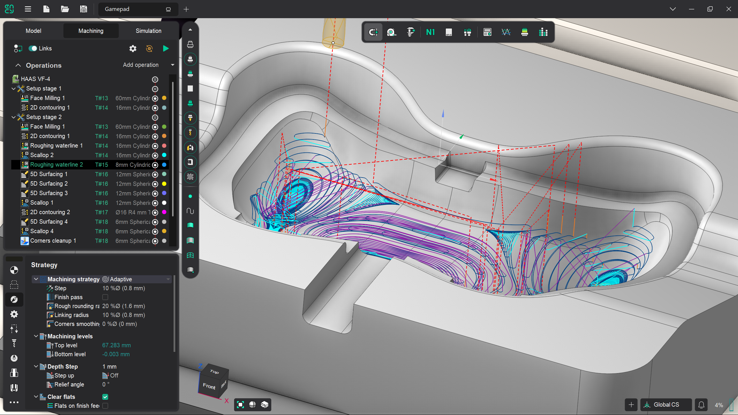
CAM software is designed to support a range of machining tasks, from simple 2.5D pocketing to full 5-axis contouring. Its primary purpose is to convert geometry into executable motion — reliably and repeatedly. The toolpath generation process accounts for part geometry, stock conditions, tool geometry, and machine constraints. By simulating this process virtually, CAM helps identify potential issues like collisions, overtravel, or uncut areas before they reach the machine.
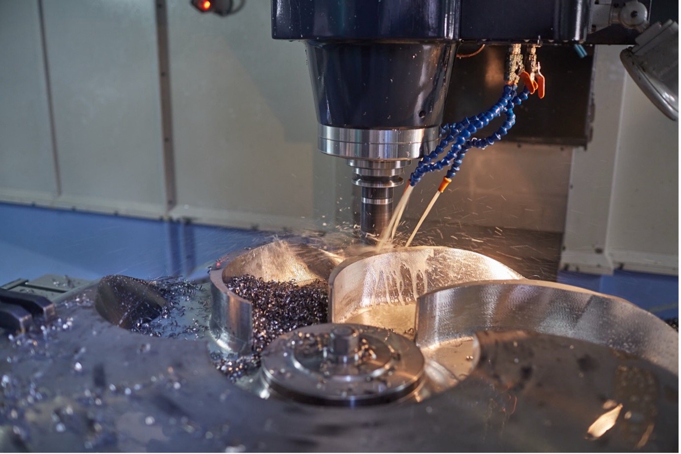
Typical operations include facing, slotting, contouring, drilling, tapping, 3D surfacing, and complex finishing strategies. CAM is used not only in mold and die shops, but also in aerospace part manufacturing, precision medical device production, and custom component machining. For example, a single impeller made from titanium may require simultaneous 5-axis roughing, multi-tool finishing, and specialized post-processing — all of which are coordinated within a CAM system.
CAM systems are used to automate toolpath generation and machine code output, reducing the need for manual intervention. This automation enables a more efficient manufacturing process by eliminating repetitive programming tasks and minimizing errors during the setup of complex jobs. In workflows that combine CAD and CAM, designers and machinists can iterate faster and bring a product to market more quickly.
Industry Applications of CAM Technologies
CAM technologies are used across a wide range of industrial sectors, each with its own manufacturing demands, part geometries, and regulatory standards. While the core functionality of CAM systems — generating toolpaths, simulating machining, and post-processing for CNC machines — remains the same, the context of application varies significantly by industry. Below are five representative sectors where CAM has become essential to production workflows.
Aerospace and Defense
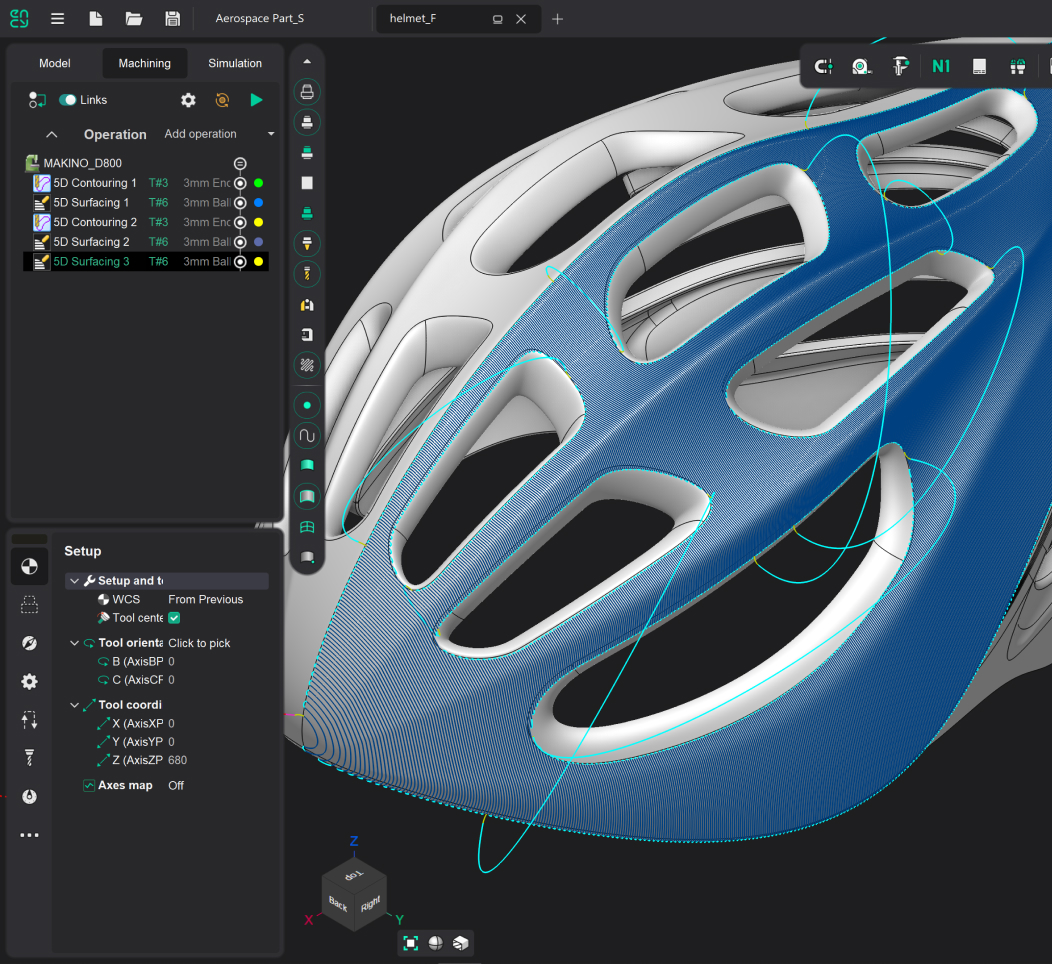
The aerospace industry demands precision, repeatability, and strict compliance with certification standards. CAM systems in this sector are primarily used for machining complex 5-axis components such as turbine blades, structural frames, engine housings, and high-performance brackets.
Many aerospace parts are made from hard-to-machine materials like titanium alloys, Inconel, and composite laminates. These materials require fine-tuned cutting strategies to control heat, minimize vibration, and reduce tool wear. CAM software must support multi-axis roughing and finishing, toolpath optimization for thin walls, and highly accurate simulation to avoid costly scrap.
Aerospace manufacturers also emphasize traceability and digital documentation. Therefore, CAM must be tightly integrated into PLM systems and support revision control, part history tracking, and quality reporting. Implementation in this sector often involves complex machine-tool setups and specialized post-processors tailored to 5-axis gantry machines or horizontal machining centers.
Automotive Industry
In automotive manufacturing, the primary challenges include mass production, material variability, and process efficiency. CAM is widely used in both high-volume environments (e.g., engine block machining, transmission parts, stamping die production) and custom manufacturing (e.g., prototyping for new vehicle platforms or limited-run performance components).
Cycle time optimization is critical, so CAM systems must deliver efficient toolpaths that reduce idle time and machine downtime. Machining cells are typically automated with integrated probes and tool changers, which require accurate NC programming from the CAM side. Typical operations include high-speed milling, deep drilling, and coordinated multi-station setups.
CAM implementation in automotive plants is usually embedded in a broader digital manufacturing system, where CAD, CAM, MES, and ERP are interconnected. Tool libraries, machining templates, and machining knowledge databases are often shared across production sites to ensure global consistency and compliance.
Medical and Dental Manufacturing
The medical sector demands extremely tight tolerances, high-quality surface finishes, and full compliance with industry regulations. CAM is widely used for producing orthopedic implants, dental prosthetics, surgical tools, and custom patient-specific parts.
These components are typically made from biocompatible materials like stainless steel, cobalt-chrome, and titanium, which are challenging to machine. CAM software must support micromachining strategies, precise control of surface finishing, and validated post-processing routines for highly specialized CNC equipment.
Customization is common in this industry, particularly in dental milling centers where each part is unique. CAM platforms need to process STL data, support automated nesting, and optimize material usage. Implementation often involves direct integration with 3D scanning and modeling tools to form a complete digital workflow — from patient scan to milled implant.
Tool and Mold Making
Toolmakers and mold shops rely heavily on CAM for producing injection molds, die-cast tools, and stamping dies. The geometries are complex, often involving deep cavities, undercuts, and tight-fitting inserts. CAM is essential here for both roughing and multi-surface finishing, including high-precision strategies like pencil milling, rest machining, and Z-level passes.
Because of the high cost of mold materials (e.g., tool steel) and the value of finished tools, simulation accuracy and collision avoidance are especially critical. CAM software in this segment must support tool holder definitions, realistic stock models, and collision-safe retraction paths. Machining time is typically long, so automated toolpath optimization and high-efficiency strategies like trochoidal milling are used to reduce cycle times.
In many cases, CAM is also used to program EDM (electrical discharge machining) and electrode production, making it part of a broader workflow that includes both subtractive and finishing technologies.
Consumer Electronics and Precision Engineering
Manufacturers of smartphones, wearables, optics, and small mechanical assemblies use CAM to handle miniaturized parts, delicate materials, and tight dimensional tolerances. Aluminum, magnesium alloys, plastics, and glass-like composites are commonly used in this field, requiring fine control of feedrates, engagement, and tooling.
Parts are often thin-walled, with highly detailed features, requiring multi-axis machining and microdrilling capabilities. CAM tools must account for machine kinematics, thermal deformation, and vibration-sensitive setups. Tool libraries may include custom or proprietary cutters that require fine-tuned CAM settings.
Implementation in this field focuses on automation and repeatability. CAM platforms often work alongside automated inspection systems and robotic part handling to minimize manual labor. High-speed machining, short cycle times, and rapid design changes are standard, making CAM + CAD integration a necessity to maintain productivity and reduce time-to-market.
The CAM Workflow
The typical CAM process begins when a 3D model is imported from a CAD system. The programmer defines the stock size, machine setup, fixtures, and coordinate systems. Next comes toolpath creation — selecting strategies appropriate for the geometry and material, setting cutting parameters, and choosing suitable tools from the library. The software calculates the path, simulates the material removal, and highlights any errors or inefficiencies.
Once verified, the toolpath is converted into machine-specific code using a post-processor. The result is a clean, executable program that can be transferred directly to the CNC controller. Modern platforms often support advanced simulation, including visualization of the machine’s kinematics and tool engagement, to further validate the outcome. In systems like ENCY, this process can be completed in a single interface, allowing real-time feedback and faster optimization.
Advantages of CAM Software
The benefits of CAM software are reflected both in process efficiency and in business performance. CAM dramatically reduces the time required to prepare machining jobs, especially when compared to manual or conversational programming. Toolpaths are not only faster to produce but are also more consistent, reducing the risk of operator error and improving quality control.
Another major advantage lies in simulation and verification. By catching collisions, toolholder interferences, or impossible moves before code reaches the machine, CAM helps avoid costly mistakes and material waste. In high-mix environments, repeatability becomes a strategic asset — proven strategies and templates can be reused, ensuring reliable outcomes across similar parts. For production environments, the ability to standardize operations and share configurations across machines reduces downtime and increases throughput.
ENCY is a CAD/CAM ecosystem that streamlines the path from design to finished parts. Precision, speed, and efficiency—all in one solution.
- Machine-aware toolpaths
- State-of-the art simulation
- NC-code verification
- Cloud collaboration
Limitations and Considerations
Despite its strengths, CAM software also introduces certain challenges. The initial investment — in licensing, training, and suitable hardware — can be significant, especially for small shops. Some CAM systems also require substantial time to master, particularly when programming complex 5-axis parts or customizing post processors.
Additionally, the quality of the input CAD model heavily affects CAM performance. Poorly defined geometry, missing features, or intersecting surfaces can confuse automatic feature recognition and lead to failed calculations. Simulation accuracy depends on correct machine definitions and tool parameters; mismatches between virtual and real-world setups can result in incorrect or inefficient toolpaths.
These issues are manageable, but they require disciplined workflows, experienced users, and vendor support to overcome. The most successful CAM implementations tend to be those that pair technical capability with good organizational habits.
Common Implementation Issues and Solutions
When transitioning from manual to CAM-driven programming, manufacturers often encounter practical difficulties. One common issue is underestimating the learning curve. Even experienced machinists may need dedicated time and guidance to become confident CAM users, particularly when moving beyond basic 2D operations.
Another frequent challenge involves post-processors — the software components that translate internal toolpaths into code specific to a CNC controller. If these are not properly configured, machines may receive incorrect commands, leading to unexpected behavior or safety issues. Working with verified post libraries or vendor-supported customization is critical, especially for multi-axis or multi-channel machines.
Data integrity is also a concern. Inconsistent model versions, incorrect tool libraries, or outdated machining parameters can all undermine productivity. Standardizing part libraries, tool data, and templates is a practical step that helps ensure long-term consistency and reliability across projects.
Integration with CAD and CNC Systems
Effective CAM tools do not operate in isolation. They are tightly linked to both design and manufacturing infrastructure. Integration with CAD systems allows CAM to receive updated part models without reprogramming from scratch. Associative modeling ensures that changes in geometry can be propagated automatically through toolpaths.
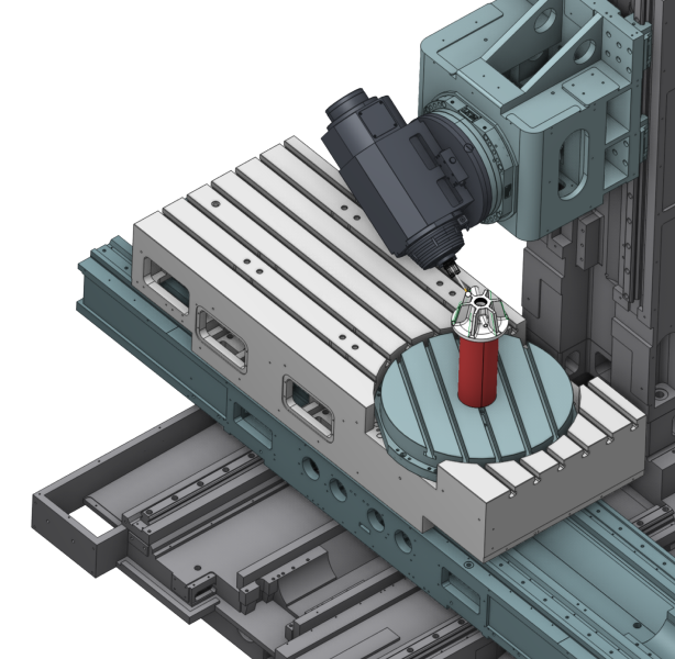
On the other end, integration with CNC controllers requires accurate simulation of kinematics, axis limits, and post-processing syntax. CAM systems typically offer digital machine models, axis visualization, and cycle time estimation to align with real-world constraints. Some platforms also support connectivity with MES (Manufacturing Execution Systems) and tool management systems, providing deeper visibility across the production environment.
Starting Requirements: Skills, Software, and Hardware
To begin working with CAM software effectively, a few basic components are essential. From a hardware standpoint, users need a workstation with a modern multi-core CPU, at least 16 GB of RAM, and a discrete GPU for simulation rendering. Software must support relevant machine types and operations — 3-axis milling, lathe programming, or multi-axis toolpathing — depending on the facility’s equipment.
Equally important is human capability. Basic understanding of machining principles — feeds, speeds, stepdowns, tool selection — is required. Many systems offer built-in learning aids, visual hints, and help libraries to reduce the entry barrier. Still, structured training is often necessary to build practical proficiency and avoid costly mistakes during the learning phase.
Master all features of ENCY through our comprehensive video tutorials. Start from interface basics to advanced machining strategies.
- Step-by-step software guides
- Real project examples
- Get ENCY Certified upon completion
Transitioning to CAM: Process and Cost
Implementing CAM within a manufacturing operation is both a technical and organizational shift. The process typically starts with pilot projects — existing parts with known machining history are reprogrammed using CAM to compare efficiency and accuracy. These early projects help refine templates, validate post-processors, and build operator confidence.
The next step involves onboarding staff through training, standardizing libraries, and gradually expanding CAM usage to more complex or higher-volume components. Implementation timelines vary, but most organizations reach productive deployment within three to six months.
Financially, CAM investment includes license fees (which can range from $2,000 to over $10,000 depending on modules), training costs, workstation upgrades, and post-processor configuration. Maintenance and support contracts are usually billed annually and represent 15–20% of the license cost. Despite the upfront investment, return on investment is often achieved within the first year, especially when CAM replaces manual or semi-automated workflows.
Common Mistakes in Computer-Aided Manufacturing Adoption
Even with the best intentions, organizations sometimes struggle during CAM adoption. Over-customization of the interface or post-processors can backfire when updates are released. Neglecting to validate first runs — for example, by testing new programs on soft materials — can lead to unnecessary downtime or scrap. Poor data organization often results in duplicated efforts and inconsistencies between jobs.
A frequent error is treating CAM software as a black box. While automation can suggest toolpaths and strategies, programmers still need to understand how and why certain settings affect cutting dynamics. Without this knowledge, it’s easy to trust an incorrect simulation or overlook subtle errors.
Avoiding these mistakes requires a blend of training, documentation, and vendor collaboration. Creating standard templates, checklists, and process documentation greatly improves consistency and reduces onboarding time for new team members.
Return on Investment (ROI)
The ROI from CAM software depends on the scale and complexity of operations, but in nearly all cases, the impact is measurable. For high-mix job shops, CAM reduces the overhead required to program parts manually. For production environments, toolpath optimization and cycle time reduction translate into higher machine utilization and lower unit cost.
Savings also come from error reduction. By simulating and verifying jobs before they reach the floor, CAM helps eliminate rework and scrap. In environments where tight tolerances and exotic materials are common, this can mean thousands of dollars saved in avoided waste.
In typical cases, programming time is cut by 40–60%, scrap rates drop below 2%, and time-to-market is shortened. These gains, combined with improved repeatability and flexibility, make CAM one of the most impactful digital tools available to manufacturers.
Conclusion
CAM software is no longer an optional tool for machine shops — it is a core element of competitive, digitally driven manufacturing. It replaces manual effort with reliable automation, accelerates programming, reduces risk, and enables smarter use of equipment and personnel.
As part geometries grow more complex and production timelines shrink, CAM enables teams to respond with agility, accuracy, and confidence. Whether you’re working on a prototype or producing thousands of precision components, mastering CAM is a strategic investment in the future of your manufacturing operation.
